|
Ludlow Valve Mfg. Co. - Troy, NY Ludlow Valve was founded by Henry G. Ludlow in 1866 in Waterford, NY and started producing fire hydrants that same year. In 1872 Ludlow Valve moved to Lansingburgh, New York. As noted on this company letterhead of 1874, Ludlow moved to Troy, New York, shortly thereafter and remained in Troy until the company went out of business 1969. Before Ludlow Valve closed it acquired Rensselaer Valve also from Troy. Fire hydrants manufactured by Ludlow Valve after acquiring Rensselaer Valve were cast with the manufacturer noted as "Ludlow - Rensselaer" Parts for Ludlows and Rensselaers are manufactured by Trumbull Industries in Youngstown, OH for two of Ludlow's most common models, the List 75 and the List 90. | ||||
|
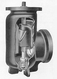
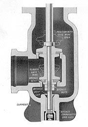
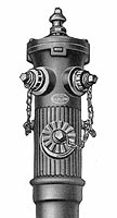
| Ludlow's slide gate was their most commonly used main valve design. The image and text below are from a Ludlow Valve catalog dated 1940. |
|
"The soundly engineered wedge lock principle and its simple sturdy construction forms the basis
of the Ludlow superior fire hydrant design. The mechanism is a simple sliding gate which travels on a central stem. In opening, the first turns of the stem unlock the works, back off hte gate away from its seat, and close the drain valve in the extreme bottom of the hydrant. The gate then travels up on the bronze screw of the main stem. In closing these movements are reversed. After downward travel is stopped there is a horizontal movement, and the rubber-faced gate is wedged to a bronze seat by a heavy, solid bronze wedging stem nut mving on the hard chilled face of a spline in back of the hydrant and the chilled inclines on the gate. The last turns of the stem automatically open the drain valve and bring locking nuts into engagement which prevent any release of the main valve mechanism. Thereby the closed and locked mechanism is shock proof and non-flooding." |
|
|
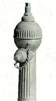
Patent What is believed to be the first Ludlow model, the Patent, looks like a bowling ball mounted to top of a post. The barrel is a 1-piece design. |
| List 75 - 2" This small hydrant bears no resemblance to the common List 75 but a 1940 catalog labels this as a 2" No. 75 hydrant. |
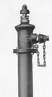
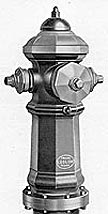
| List 75 This model enjoyed a 70+ year production run; during which the 1-piece barrel was dropped in favor of a 2-piece barrel. Multiple valve versions of the 1 pc. barrel List 75 were produced as well. The List 75-0 was a later model development with a much larger weather cap. |
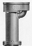
| List 78 This model is a flush hydrant based on the List 75 model. |
|
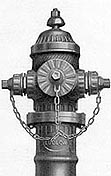
List 85 This model is very similar to the List 75 hydrant except that a flange is provided under the nozzles so that they can be turned to point in any direction. Readers are encourage to submit photos of actual hydrants to this website. |
| List 90 This model has the unmistakeable octagonal shaped barrel, bonnet, and nozzle caps. A later model development, called the List 90-0, has exposed bonnet holddown nuts/studs. |
|
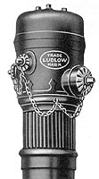
| Ludlow's balanced valve design was ingenious but likely not cost competitive for widespread usage. The image and text below are from a Ludlow Valve catalog dated 1940. |
|
"The balanced valve design was manufactured to meet the demand for a non-freezing hydrant
which could be easily and satisfactorily operated under high pressures. It can be operated
more easily than any other compression type hydrant now being manufactured. In operation the upper valve opens with the pressure and the lower valve against it. The valve spool or double header is always in equilibrium and can be opened and closed without any effort. The valve is faced with solid rubbers of the same special quality as furnished with the Ludlow Slide Gate Hydrant. The drop valve is simple in construction and postive in action. As the hydrant is opened, the drip or waste outlet is at once closed, the drip valve being drawn up into the bronze drip cylinder. In closing the hydrant, the drip valve is pushed out of the bronze cylinder into the flared lower end of same. The water in the stand pipe then passes out through the corrugations of the bronze guide on the lower end of the stem." |
|
|
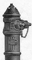
List 80 This model is a low/ medium pressure hydrant based on the High Pressure hydrant. It's bonnet lacks the ornateness of other Ludlow models. |
| High Pressure This model bears some resemblance to the List 75 Multiple Valve hydrants but is internally identical to the List 80 model. |
|
Patent | List 75 - Part 1 , 2 , 3 , 4 | List 80 & Hi-Pressure | List 90 |
|
|
|
|
| Unless otherwise noted, all contents of these WWW pages © FireHydrant.org |