Drafting From Low Pressure Hydrants
Part Five
© 2001 Capt. Willis Lamm, Water Supply Officer, Moraga-Orinda (CA) Fire District

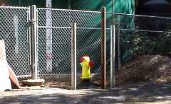
The following procedures are examples of low water pressure evolutions based on the procedures of the Moraga-Orinda Fire District, presented for illustrative purposes.

This hydrant is connected to the Canyon School water tank via a dedicated 6" line. Since the hydrant is at the same level as the tank, it has an average static pressure of only 7 psi with an available flow at normal head pressure of about 315 GPM. However by using hard suction, flows of about 850 GPM can be obtained.

Typically about 20,000 gallons of water are available from the tank.

Hydrant outside the fence,
protected by ballards

  GETTING EFFECTIVE WATER SUPPLY

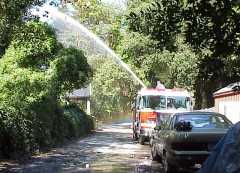
A logical operational sequence to provide water supply and still maintain roadway access along Northern Railway is as follows:
  • First in engine does size-up and attacks the fire from the booster tank.

  • First arriving engine equipped with hard suction hose takes a position as close to the pump house fence as is practical and establishes hard suction.

  • Next arriving engine without hard suction drops a supply line and lays to the fire (if beyond the hydrant.)

  • Relay pressure should be 150 psi if using a dual lay of 2½" hose, or 100 psi if supplying LDH.

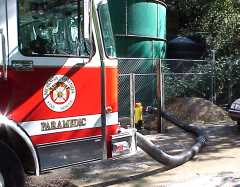
The roadway is narrow so tight, parallel parking is important.

An appropriate sequence of actions is:

  1. Remove the hard suction hose and 4½" double female adapter from the engine.

  2. Remove the front soft suction and 6"x4½" reducer.

  3. Attach one length of hard suction to the front suction connection.

  4. Attach the double female adapter to the hydrant.

  5. Attach the 6" x 4½" reducer to the second length of hard suction and connect it to the hydrant.

  6. The reason we connect the two pieces of hard suction last is in the event the engine has to be repositioned to make the hookup, one person can hold the hose while the engine is moved.

  7. The front suction drain can be opened to purge air from the hose and hydrant pressure should be sufficient to purge remaining air from the system running the pump at moderate idle speed.
Hard suction layout
Discharging 850 GPM


Return to Drafting from Low Pressure Hydrants Index

Return to Water Supply Index

Back to Information Section


  Back

Legal Disclaimer

Unless otherwise noted, all contents of these WWW pages © 1996-2002, FireHydrant.org