|
The following procedures specifically apply to the Knickerbocker Ln. system and generally
apply to all dry systems.
First Arriving Engine
|
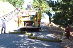
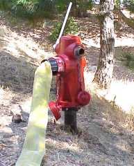
First arriving engine laying
from "dry" hydrant
|
|
Second Arriving Engine
- Lay supply line from the dry hydrant to the first arriving engine (if line not already established.)
Notes: If supply line is already established, proceed directly to provide a 2-in 2-out rapid intervention team.
Unless the first arriving engine is spotted at the hydrant, someone will need to stand by the
hydrant to bleed air and open the discharge to the supply line.
|
|
Third Arriving Engine
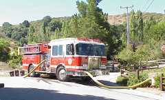
- Spot to make a front suction connection to the hydrant at the Knickerbocker Ln. cul de sac.
- Be careful with apparatus placement and take a few spiral twists in the suction hose to
prevent kinks.
- Spotting the engine facing downhill will put the FDC within reach
of a 100 ft. length of hose.
|
Supply engine making hookup
|
|
- Pull 100 ft. of large diameter hose (LDH) from the engine to the FDC.
- Place a 4˝" x 2˝" reducer on the hose prior to connecting to the FDC. (This sequence
allows the FDC swivel to work.)
- Connect the FDC hose to the LDH discharge on the engine.
|
Hooking up to the FDC
|
|
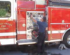
Supply Engineer
|
Running pressure to 150 p.s.i.
|
|
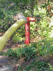
Hydrant Person
- Bleed off all air using the 2˝" discharge outlet.
- When the engine at the scene is ready, completely open the LDH hydrant outlet.
7-26-00 TEST RESULTS
Knickerbocker supply hydrant:
|
Static Pressure:
Residual Pressure: (@ 1000 GPM)
|
35 p.s.i.
10 p.s.i.
|
Dry (discharge) hydrant:
|
Static Pressure:
Residual Pressure: (@ 1000 GPM)
|
112 p.s.i.
18 p.s.i.
|
Note:
We did not test this evolution using 2˝" hose.
A dual lay would be required to deliver 1000 GPM. Based on rule-of-thumb,
the discharge pressure from the supply engine would have to be increased by 40
p.s.i. for every 100 ft. of double lay used. (This would calculate to a minimum of
40 p.s.i. additional pressure required for the hose lay between the engine and the FDC.)
Additional evolutions will be presented
in this same format
|
Bleeding off air
before charging hose
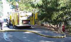
Supply established to first engine
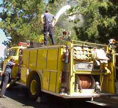
Flowing 1000 GPM.
|