|
The Design and Manufacture of Fire HydrantsDesign Project #1: Casting Manufacturing Methods Spring 2000 Dr. K. Mazouz Due: March 3, 2000 By: Elissa M. Wahlstrom & John J. Barrett 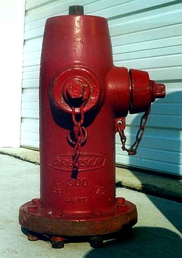
Special Thanks to: Douglas B. Watson, Driver/Engineer Palm Beach County Fire-Rescue West Palm Beach, Florida Florida Atlantic University Department of Mechanical Engineering Abstract
Table of Contents
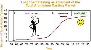
Introduction When designing a process to cast fire hydrants, several factors must be taken into consideration such as materials to be used, environmental factors, cost, etc. Once a general guide for specifications is obtained from the customer, an overall design process begins to take shape. This design process is then configured in a step by step procedure to guarantee that no oversights in regards to design are made. After the design process is set, manufacturing of the mold, and core if necessary, can begin. If the design process is done properly, it will naturally lead into a step by step procedure for the manufacturing process. During all steps of the manufacturing process the hydrant will be checked against the customer specifications to ensure a quality product is being produced. This quality control process encompasses the production of hydrants from the initial design stages to finished product. Upon receipt of the customer specifications, the design process begins. Questions of how to incorporate these specifications into existing designs or create an entirely new design are posed at this point. For example, what kind of system is needed to attach the hydrant to the water supply, what is the pressure in the water lines connected to the hydrant, and what valves are needed in regards to the above questions. All of these questions must be answered in the preliminary stages of design. After the initial information of the first stage of preliminary design is established and a suitable existing design is found, more detailed design can begin. This will incorporate considerations such as choice of material, tolerances of parts, and designation of a process. Included in these areas are the materials available for use, cost analysis, aesthetic needs, etc. All these choices are related as well. For example, the choice of casting method must take into consideration the material being cast. A process must be chosen that will maintain the integrity of the material. Each process must be weighed for advantages and disadvantages and compared to the overall concept of design. When preliminary design is complete and materials and a casting process are fixed, the actual detail design can begin. General guidelines of specifications now become very specific including acceptable error or tolerance ranges. Calculations for oversizing, heat transfer, pouring temperature, pouring speed, etc. are made and applied to the overall design. Fortunately, with fire hydrants, as with most castings, there is already a similar design in place that can just be modified to fit the customer specifications. When this is the case, the design process can be considerably shortened when compared with having to design a new process from scratch, which can include, but is not limited to new mold design, making a sample, etc. After the design process is finished and a set of procedures is established, the manufacturing process can begin. It should be noted however that the manufacturing process is designed for the hydrant in the design stage. Any adjustment to in-place procedures must be prior to production. The materials for the mold have already been selected and must now be assembled to finish the construction for the fire hydrant mold. Processes for pouring and solidifying must be confirmed and documented as well. After the casting process has been completed all post casting processes such as machining, painting, attaching fittings, etc. must be documented and completed in order to provide the customer with a total quality product. Casting Processes In order to gain a better understanding of the manufacture of a fire hydrant, it is useful to know the theoretical background of casting. Casting is a process by which molten metal flows by gravity or other force into a mold where it solidifies in the shape of the mold cavity. This process is approximately 6000 years old, making it one of the oldest shaping processes. Since this process can be used to produce a wide variety of parts with respect to size and composition, it is appropriate to state that casting is one of the most versatile processes in manufacturing as well. One interesting aspect of castings is that they do not have directional properties. This means that the strength, ductility and toughness are equal in all directions.7 There exists a variety of casting processes and certain characteristics are incumbent on each. To name a few, we have: ·Sand Casting ·Shell Molding ·Vacuum Molding ·Centrifugal Casting ·Die Casting ·Lost Foam Casting Sand casting is the most widely used and it one of the few processes that can be used for metals with high melting temperatures such as steel, nickel and titanium. The simplest process of sand casting includes pouring the molten metal into a sand mold usually made as a composition of silica, water and clay, allowing the metal to solidify and then breaking up the mold to remove the casting. Subsequent operations on the cast part usually include machining, cleaning, inspecting and possible heat treatment. Traditionally, this type of casting has been used in the manufacture of fire hydrants since their invention in the early-1800's.14 Following recent developments in casting processes, some companies have been straying away from the traditional sand casting and, instead, utilizing this new technology. The development at hand is called the lost foam process and it will be discussed History of Lost Foam Casting In 1958, H.F. Shroyer patented the use of foam patterns for metal casting. It consisted of a pattern machined from a block of expanded polystyrene (EPS) and supported by bonded sand during pouring. In this process the polystyrene is evaporated when the molten metal is introduced to allow the formation of the cast object. This is not, however, lost foam casting, but full mold process. The only difference between the two processes is the use of bonded or unbonded sand for support. It was not until 1964 that the first lost foam casting was performed by M.C. Flemmings.16 The first public acclamation of the benefits from lost foam was through a General Motors project in 1993.6 By 1998, production by use of lost foam casting had reached approximately 140,00 tons in the United States alone. And in 2005 it is forecasted that lost foam casting will account for 29% of Aluminum and 14% of Ferrous Casting markets.6
There are several steps to this process and each is explained in detail below.16 1.Pre-expanded beads, usually polystyrene, are blown into a mold and therefore forming the pattern sections. These sections can then be glued together to form a cluster. 2.Once the beads are in place, the mold goes through a steam cycle that results in the interfusing of the beads due to their full expansion. 3.Now a barrier must be formed that separates the molten metal from the surrounding sand. To accomplish this the hydrant pattern of polystyrene is covered with ceramic coating. This coating does not only prevent sand erosion, but also protects the structural integrity of the product. Application of this coating can be applied through either dipping, spraying, or pouring. 4.For stability, the pattern must be supported in the flask by the surrounding sand. Due to the complexity of the geometry of a hydrant, or any other cast part, the sand might not easily reach into certain areas. The proper compaction of the unbonded sand around the pattern can be ensured by using a vibration table. Care must be taken to compact the sand without distorting the somewhat flexible coating. 5.The molten metal will then be poured directly into the foam pattern, decomposing the foam and therefore forming the cast product, or hydrant. 6.The sand is removed from the flask and the casting is cleaned and inspected before further assembling operations. With the increased use of this type of casting of the last decade, it is evident that the benefits of lost foam casting are indeed significant. An explanation of these benefits is listed below. As with other casting processes, the accuracy and tolerances will vary according to the size and complexity of the geometry of the part. However, the manufacturer can expect to achieve tolerances that equal, if not surpass, those of shell mold and permanent mold processes. The downside to Lost Foam is that warped, distorted, and defective castings can result without proper control. The surface finish is significantly improved over traditional sand castings due to the thin protective coating surrounding the smooth foam pattern. With the existence of a smooth surface finish after casting, the machine and assembly requirements are substantially reduced or eliminated. The table below illustrates this benefit.  Solid waste and environmental emissions are significantly reduced. This benefit proves useful for not only for the environment, but also the manufacturer since solid waste is an increasingly burdensome capital cost, especially in green sand and no-bake foundries. The versatility of this process is depicted by its ability to cast parts ranging from less than one pound up to thousands of pounds, although most cast products are less than fifty pounds. A major consideration when given product specifications from a customer is the type of material that will be used to produce that product. Because often times the customer is not knowledgeable about the processes to make a specific part, it is up to the manufacturer and designer to be thorough in his/her analysis of the type(s) of material(s) to use. The material chosen must satisfy all the structural considerations, quality issues, cost issues, and on a smaller scale aesthetic needs. The materials must be considered to give optimal conditions at the lowest possible cost. For a fire hydrant some structural considerations include internal pressure, vibration effects from the environment, and abrasive wear due to external and internal environments. These considerations directly relate to a need for high compressive strength, good vibrational damping, high impact strength, and good abrasive wear resistance. While many materials may have these properties, the material which has these properties at the lowest cost to manufacture is gray cast iron.5
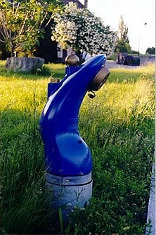
Another important consideration for fire hydrant materials is the material from which the fittings are made. (The fittings are the brass "threaded outlets.")8 It is pertinent that the fittings withstand corrosion and wear so that they can be used properly and easily by firefighters. Brass fills this need at a relatively low cost when compared to corrosion resistant alternatives such as titanium and cobalt5. The purpose of a fire hydrant is to serve as a valve between the underground water supply and a pump aboard fire department apparatus. Keeping this in mind, several design considerations can be formulated. Aside from the structural requirements of the metal, the geometry of the hydrant itself must enable sufficient use of its intended task. While there is quite a variety in the shapes and sizes of hydrants throughout the world, they all possess a few common characteristics. Listed below are some of these traits.
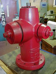
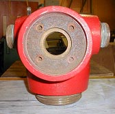
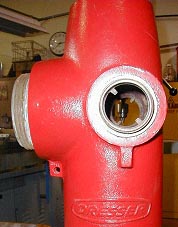
Notice some minor details such as the odd shaped nuts on the caps and top valve piece. It is an unusual pentagonal shape probably meant to reduce the possibility of unauthorized use. Also, notice the built in latches under each connection. These are present to prevent misplacement or theft of the caps when a chain is in place. The chain stretches from the hole to the groove in the cap. The first thing that must be done in the manufacturing of the hydrant is to form the polystyrene pattern of the various sections. In this case, a total of five different patterns must be created using methods that have been previously defined in this report. These sections are as listed:
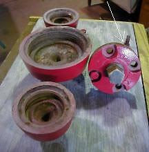
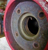
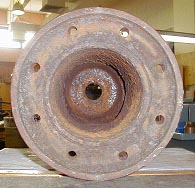
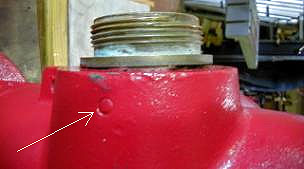
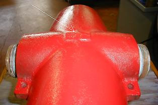
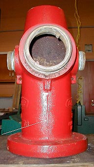
Since the use of Lost Foam Casting eliminates the need for cores, the inside aspects of the hydrant must included in the pattern creation. These aspects are illustrated below. The pictures directly below show the geometry of the seat of the valve mechanism at the top of the hydrant. It is essential that the dimensions of the inner shaft be accurate to prevent leakage. By using lost foam casting, these tight tolerances are easier to obtain than traditional methods. Also, notice that the screw holes do not penetrate through to the other side of the seat. This serves as another precaution to prevent leakage. The threads will have to be machined after casting.
Lost foam casting is becoming a popular alternative when casting is the desired method of production. This casting method provides for good dimensional accuracy and tolerances and good versatility in range of application. For manufacturers wishing to reduce environmental impacts and solid waste costs, lost foam casting provides an extremely attractive alternative. When considering the casting of fire hydrants, in particular, lost foam casting is slowly becoming popular. The concept of coreless casting makes lost foam an ideal choice for hydrants. This process also eliminates the parting line caused by the cope and drag. And even the cast irons used for hydrant casting can have a good surface finish with lost foam casting. Gray cast iron is the material of choice of fire hydrants. Gray cast iron provides good compressive strength, high ultimate strength and good vibrational damping. A fire hydrant needs to be strong enough to withstand high stress applications. Gray cast iron fills this need. Other design considerations are size and number of fittings for hoses and a robust body that will resist the effects of corrosion and pressure. All of the above design considerations give rise to the manufacturing considerations. In the example used, the main cylinder, the caps and the cast iron portion of the valve assembly must have polystyrene patterns made. Certain characteristics for a water-tight seal must be maintained. The lost foam casting process, with its good dimensional tolerances, helps to achieve this. While still more expensive than traditional sand casting lost foam casting is becoming a viable alternative to many casting applications. It is still relatively new in the fire hydrant industry, but with all the benefits of lost foam casting, it has a definite place in manufacturing today. References: 1. Anderson, Dave. Foundry personnel. M&H Valve and Fitting Co., Anniston, AL. Interview by telephone on 23 February 2000. 2. Askeland, Donald R. The Science and Engineering of Materials. Third edtion. Boston: PWS Publishing Company.333-415. 3. Dr. Askeland, Donald R., Ph.D., Professor, Distinguished Teaching Professor. Department of Metallurgical Engineering, University of Missouri-Rolla. Interview by telephone on 28 February 2000. 4. Dr. Bates, Charles, Ph.D., Case Institute of Technology, Research Professor of Materials Science and Engineering, Director, METALS Technology Laboratory, University of Alabama Birmingham. Interview by telephone on 28 February 2000. 5. Beeley, P R. Foundry Technology. Boston: Newnes-Butterworths, 1972. 1-431. 6. Norvil Foundry. Ballarat, Victoria, Australia, http://www.australianfoundries.com/norvil/next.htm . February 2000. 7. Groover, Mikell P. Fundamentals of Modern Manufacturing: Materials, Processes, and Systems. New York: John Wiley and Sons, Inc. 240-294. 8. "Lost Foam Casting." http://www.eng.uab.edu/mte/MtE%20Labs/Metals%20Technology%20Center/Lost%20Foam%20Casting.htm. 24 February 2000. 9. "Lost Foam Foundry." http://www.hopkinton.org/water/fireflows.htm. 23 February 2000. 10. Massey, Brian. Foundry Manager. Mueller Company, Albertville, AL. Interview by telephone 22, 25 February 2000. 11. "Most Asked Questions About Lost Foam Casting." http://consoltech.net/more2.htm. 24 February 2000. 12. "Moulding Processes." http://www.dossmann.de/english/bonform.htm. 24 February 2000. 13. Quist, Jim "hydrant information." E-mail to Elissa Wahlstrom (emwah76@hotmail.com). 26 February 2000. 14. Quist, Jim "Re[2]: hydrant information." E-mail to Elissa Wahlstrom (emwah76@hotmail.com). 03 March 2000. 15. Taylor, Howard F., Merton C. Flemings, John Wulff. Foundry Engineering, New York: John Wiley & Sons, Inc.,1959. 97-104. 16. "Welcome to the AFS Homepage at the University of Missouri-Rolla." http://www.umr.edu/~foundry/first.htm. 25 February 2000. Photo References Figure 3. http://www.firehydrant.org/pictures/i/0003.jpg Location: Switzerland Photo: Copyright ©1999, David Pedrocca More Info: http://www.wagamet.ch/english/log50.htm Cover Sheet. 0181 Model: Traffic 300 Date: 1975 Size: 4 1/2 Location: John Anderson's Private Collection Photo: Copyright © 1999, John Anderson |