|
2Ẅ" and 3" supply lines
Apparatus equipped with 2Ẅ" and 3" supply lines can equip their hose loads with
"4-way valves" in order to establish rapid initial water supply (laying from
hydrant to fire) and enable a later arriving engine to relay pump without
interrupting water flow. The 4-way valve is connected to the end of the
hose load. The hydrant person attaches the 4-way valve to the hydrant while
the engine lays line to the scene. When the hydrant is opened, water is
supplied to the engine operating at the scene using hydrant pressure.
If hydrant pressure is insufficient to provide adequate flow, a second engine can
connect to the 4-way valve and increase pressure by relay pumping through the
established hose lay to the engine at the scene.
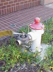
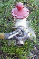
Blake 4-Way Valve
The Blake 4-Way Valve is an older device with a fairly simple operating premise.
It consists of a large ball valve which directs water in 90 degree bends
to the outlets.
During normal operation the hydrant water is directed to the left hand outlet
(as oriented to the photo) and down the supply line. The relay pumper
will connect an intake line to the right hand outlet and discharge to the inlet
that is opposite from the hydrant. When the control handle is turned 90 degrees
to the right, water is then directed through the right hand outlet to the relay
pumper. The relay pumper then discharges into the inlet opposite the hydrant
connection (bottom of the picture) to supply the hose lay.
Thanks to Oakland Sta. 24 for letting us work with and photograph their
Blake 4-way valve and 1870's "horse" hydrant.
|